1
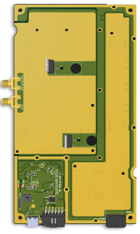
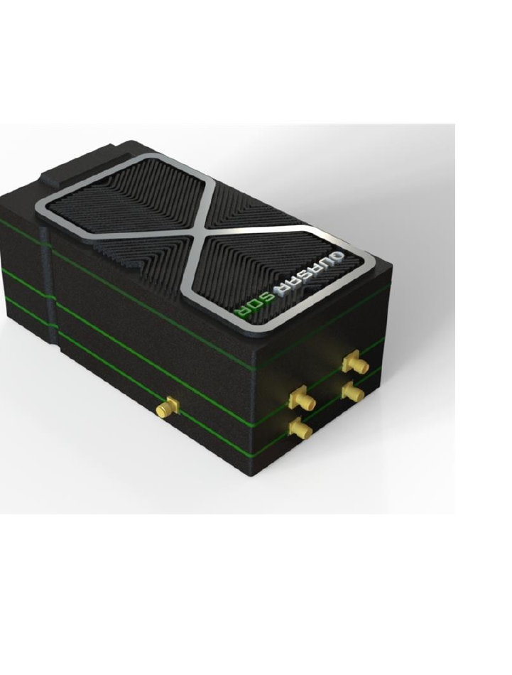
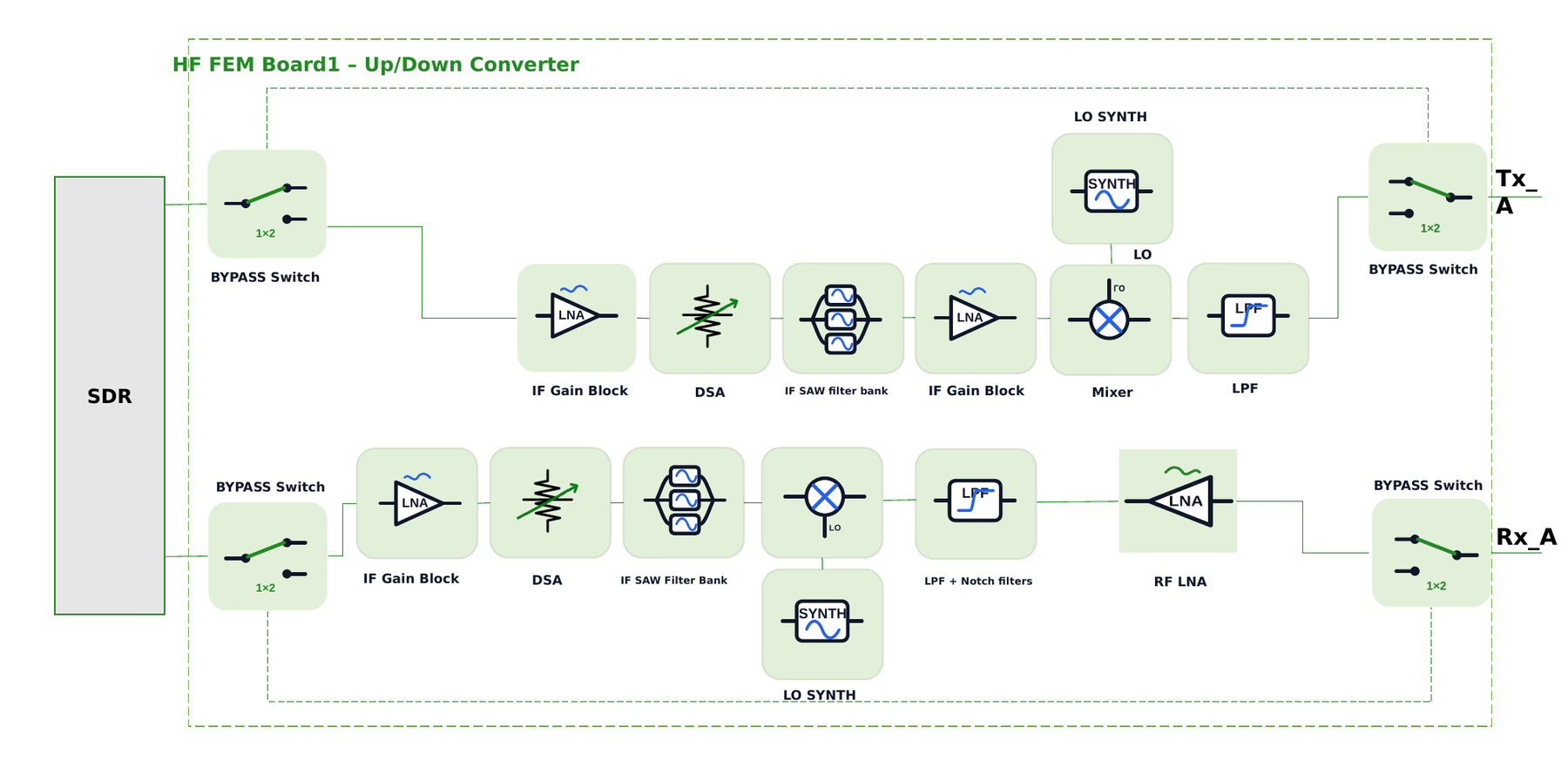
B1 — Up/Down Converter
SDR-side IF/RF conversion with filter banks and gain control
Section 1 SDR-side board. Bidirectional up/down conversion between the SDR's IF and the 1.8 – 30 MHz RF band. Includes an IF gain block, digital step attenuator (DSA), IF SAW filter bank, RF LNA, LPF + notch filtering, LO synthesizer, mixer, and bypass switches for path selection.
Key blocks
- IF Gain Block
- Digital Step Attenuator (DSA)
- IF SAW Filter Bank (3 bands)
- RF LNA
- LPF + Notch Filters
- LO Synthesizer
- Mixer
- Bypass Switches
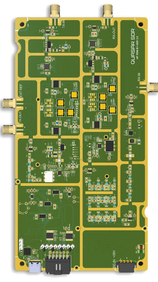
QSR-HF-B1-OCopen card